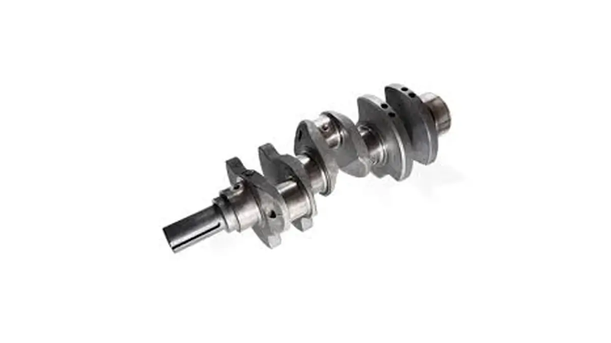
Based on the crank-slider mechanism, the crankshaft (or "crank" for those more familiar with it) is a crucial component for the proper functioning of your engine block's cycle! This part is included in the engine distribution. Discover how a crankshaft works!
In this article, we will try to answer several questions: How is a crankshaft made? What parts make up the crankshaft?
Additionally, we will try to understand how the crankshaft operates within the engine. Enjoy your reading!

Are you looking for a car scanner ?
The composition of the crankshaft
What is a crankshaft?
The first question that might come to mind is: "What is a crankshaft?". From an etymological perspective, the word "crankshaft" originates from the Dutch term "vimmelkijn", which means "auger". An auger is a tool used to drill into the ground or materials such as wood.
Historical note: Historically, it is one of the main elements of the crank-slider mechanism, which was found as early as the 2nd century in the sawmill of Hierapolis in Asia Minor (modern-day Greece).
Today, this same mechanism is implemented in the engines of our cars, using connecting rods to convert the pistons' linear motion into continuous rotary motion, and vice versa. For what purpose? To transmit the energy from the cylinders to the engine's output shaft.

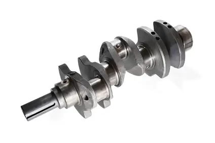
Materials – manufacturing
However, it is worth noting that depending on your vehicle, you may require different specifications for your crankshaft. For standard passenger vehicles, the crankshaft is typically made of either cast iron or machined forged steel (monobloc) to ensure durability and endurance.
If your vehicle is equipped with a turbocharged engine, for example, if you race or have decided to tune your engine, your crankshaft will likely be made of forged steel, with minimal alloy content but possibly enriched with materials such as nickel-chrome. The goal here is to have lighter components in the engine, allowing it to achieve better performance.
These lighter parts, however, are more prone to breakage, as their reduced weight also makes them more fragile.
Regular static and dynamic balancing will be necessary to ensure the crankshaft performs optimally.
How does a crankshaft work?
Now that we know the role of the crankshaft, it’s time to delve into its composition.
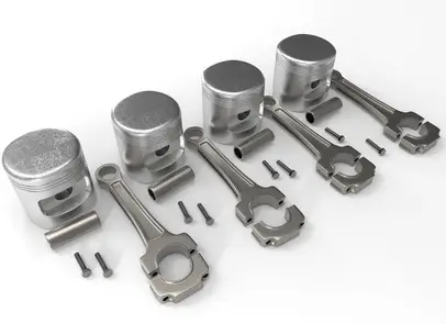
The connecting rods
As previously observed, the connecting rods are components that link the pistons to the crankshaft. In the crank-slider mechanism, the connecting rod enables the conversion of linear motion into rotary motion.
The connecting rod is a rod with two joints, one at each end, designed to transmit force and motion to the pistons. The connecting rods are attached to the crankshaft using crankpins, which in some cases may include counterweights to reduce vibrations caused by the pistons.
The journals and bearings
The journals are rotating shafts supported by bearings. The journal's purpose is to guide the crankshaft during rotation.
The journals are aligned on the crankshaft via bearings. Between these bearings, we find the crankpins mentioned earlier.
Note: The bearings are supported by seals, known as bearing seals, which can wear out over time and cause leaks. These leaks could lead to a failed technical inspection. This is why it’s crucial to monitor the components of your crankshaft carefully!
The bushings
Located between the connecting rod and the crankshaft, the bushings (or half-bushings) are components that reduce friction between the connecting rods (or the bearing) and the crankshaft. Additionally, bushings also ensure the crankshaft's lubrication.
The crankshaft is partially submerged in engine oil, so the bushings are lubricated by the oil, ensuring the crankshaft operates smoothly. It’s important to maintain the correct oil level in your engine. If the level is too low, lubrication will be inadequate; conversely, if the oil volume is too high, the crankshaft will receive too much oil.
The accessories
The crankshaft enables the activation of other engine components. On one side, the crankshaft's action activates the timing belt or chain. On the other, the crankshaft engages the flywheel, which includes the TDC sensor.
Crankshaft architecture
To understand the crankshaft's architecture, it’s helpful to remember that one engine cycle equals 720° for 4-stroke engines.
The geometry of the crankshaft can vary depending on the number of cylinders in your engine. The number of cylinders allows for more consistent piston timing, improving engine performance as it runs more smoothly.
4-cylinder engines
In the case of inline 4-cylinder engines, the pistons are timed at 180°. The calculation is as follows: 720° (one engine cycle) divided by 4 cylinders (exceptions may exist for vehicles with fewer cylinders). Variations may occur depending on the number of journals in your crankshaft.
6-cylinder engines and above
For 6-cylinder engines, using the same method, the timing occurs every 120°. In this type of engine, the crankpins are aligned in pairs, effectively creating two crankshafts for three cylinders each.
The same principles apply to 8- and 12-cylinder engines.
Other cases
For single-cylinder engines, the timing will always occur every 720°. However, for twin-cylinder engines, it depends. If the crankpins are aligned, timing occurs every 360°; if they are opposed, timing occurs every 180°.
For 3-cylinder inline engines, such as those found in Smart vehicles, timing occurs every 240°.
Are you looking for a car scanner ?